Custom made articulated arms
The specifications and descriptions shown bellow indicate the range of parameters available. This is a starting point for the dialog that allows our design and production staff to meet the customer’s requirements in the best possible way.
| Number of joints | 7 | 7 |
| Clear aperture | 16 mm | 19 mm |
| Mirrors – diameter x thickness | 25 x 3 mm | 28 x 3 mm |
| Adjustment tolerance – position | < 1 mm / meter | < 1 mm / meter |
| Adjustment tolerance – angle | < 1 mrad / meter | < 1 mrad / meter |
Optional specifications
1. Wavelength:
A range of bending mirrors is available. Typical laser beams that can be transmitted by OptoArms are: Er:YAG, CO2, Ruby, Nd:YAG, KTP, excimer, etc. In addition to specifying the wavelength, other laser beam parameters should be provided (average power, peak power, minimum spot size, pulse duration, etc).
2. Colour:
OptoArms are painted with high quality paints according to e.g. RAL 7035 (light grey), RAL 9002 (grey white), RAL 9006 (white Aluminum), RAL 9011 (black) etc. Other colours, surface structure and finish are available.
3. Counter balance:
Two basic types of counter balance are offered: “weight” type and “spring” type. The innovative “spring” type counter balance allows the arm to be folded back (e.g. for laser transportation purposes).
4. Lenses:
In order to compensate for large laser divergence, one or more lenses may be needed inside the articulated arm. The exact position of the lenses should be provided. The lenses usually have a diameter of 19 mm, in order to use the full clear aperture of the arm.
5. Nut thread type:
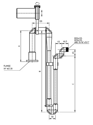
The distal end connector (exit side of the articulated arm) is typically a nut that allows attachment of various devices to the arm, such as hand-pieces, scanners, etc. Standard nut thread sizes are M23x1.5, UNS 15/16″x12/1″, and M22x1.25.
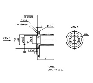
6. Flange mount:
Articulated arms are attached to the main console of the laser by the flange. The optical axis of the articulated arm is perpendicular to the plain of this flange. Standard flange designs are shown on the drawing below. The segment “A” (height of the flange) may be specified by the customer.
7. Overall length/working radius:
The total length of an articulated arm typically varies between 1.5 m and 2.0 m. Some applications may require shorter or longer arms. The working radius of OptoArms can vary typically between 0.5 m and 1.8 m. The total length of the articulated arm is determined by segments “A”, “B”; and “C”, and the working radius of the arms by the segments “B” and “C” (see drawing no. XY WZ 00).
The table bellow indicates some standard lengths of the segments. The segments’ lengths can be specified by the customer (any combination possible), taking into account technical suggestions by Optotek’s staff.
| “A” | “B” | “C” |
| 60 | 606.5 | 452 |
| 77.6 | 731.5 | 553 |
| 219 | 820 | 608 |
| 279 | 927 | 874 |
| 140 | 758.5 | 443 |
| 100 | 720 | 420 |
| 230 | 557 | 396 |
8. Joints:
A typical medical application requires articulated arms with 7 joints. Other applications may require other number of joints.
9. Right/left positioned arm:
To take advantage of the high alignment accuracy of the articulated arm, position of the arm attached to e.g. laser is important. Each articulated arm is made for right or left positioning.
“Right” positioning means that when observing from the patient (or operator or doctor) site (in front of the e.g. laser system), the long segments of the arm are seen on the right side of the attachment console (segment “A” or flange).
Vice versa, “left” positioning means that those long segments are seen on the left side. If not otherwise specified, All OptoArms are aligned according to “right” positioning definition.
10. Application:
Understanding your application will help us designing an articulated arm that will optimally suit for your needs.
11. Warranty:
One year warranty applies to all mechanical parts; warranty for optical parts depends on the warranty provided by the supplier of the optical parts.
Specify your exact articulated arm requirements, and our R&D team will be glad to assist you!